| Power for the cradle |
|
NOTE: The following describes a modification of your Palm, possibly voiding your warranty!!! A second note: After starting that page, I discovered Bens Pilot Page (UPDATE: I can't find his page anymore). He described the same idea. What I don't like, is his way to contact the free pin. I believe, solder on the golden pads is a problem. I was searching for another solution and I think I found one. I also wanted to provide a bit more information on a safe way to supply the Palm and charging the batteries. . WARNING: The Palm IIIc cradle (color Palm) uses the same pin than the following modification to supply power to the inbuilt charger of the Palm IIIc. NEVER put a Palm that was modified according to the instructions below in a Palm IIIc cradle that's connected with its original Palm IIIc power supply. That wall brick is NO charger, it's just a power supply that would ruin your NiMHs with it's 1Amp output current!!! . UPDATE: I finally changed the numbering of the pins to the 'official' standard. To make it clear once again: The pins on the cradle are numbered 1-10 from left to right looking at the cradle as it stands on your desk. Looking at your face down Palm with the connector pointing towards you, the numbers run of course 1-10 from right to left then. . |
|
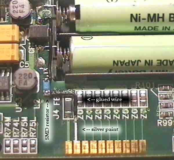
. Modifying the Palm - Pilot 1000/5000, PalmPilot Personal and Professional . When you read my page 'Power for the Palm', you've probably noticed that I'm a fan of rechargeables. I don't want to say that 3COM/USR missed something, when they left out the possibility of an external power supply. After all the Palm's a real low power device and I guess most people can live quite good with batteries. But for rechargeables it would just be nice, if they could be charged remaining in the Palm. BTW, the dot 7 command proves, that Palm did at least think about rechargeables. The craddle on the other hand is the perfect charging station (I'd wish my mobil phone charger would provide such a nice physical support ...). So my first thought, after I started using NiMHs, was how to modify the system. . Fortunately there's one pin at the serial connector, that's not in use. It's the only pin that has no visible lead into the Palm, I name it pin 9, left of it (assuming your unit is lying face down, the connector pointing towards you) is pin 10 which is ground. You need to make a connection between this pin 9 and the positive batterie terminal. Soldering on the golden pad is no good idea, cause with the proper temperature the solder will flow over the golden surface and spoil the pad. I took 'silver conductive paint' instead, to contact only the very top. I don't know where to buy that paint in the States, but stores for model-making or electronic suppliers are good addresses. Don't get me wrong, it's not any silver colored paint, that wouldn't work. It's a special, fast vaporizing fluid with disolved silver in it. After applying, it dries quickly and only a thin silver layer remains, that's an excellent conductor (BTW, years ago I repaired the heatable rear-window of my car with it. There was a little crack in that heatable serpentine lead and you can't solder it. I just painted a bit of that silver stuff over it and it works since then. Saved me alot of $$$). . For best understanding, look at picture 1 of the modification: . |
. |
| Start with the little L-shape wire, and fix it with a *little* glue.
Then fix the resistor at the one end of that wire, so you can solder it
together later. The resistor is more a protection and a good support for
the wire. The value can be anything around 10 ohm, though it shouldn't
be too high. Intelligent chargers don't like that. Take care that the end
of the wire that points towards the serial pads, ends behind the virtual
line where the bottom of the case presses onto the board. So the wire disappears
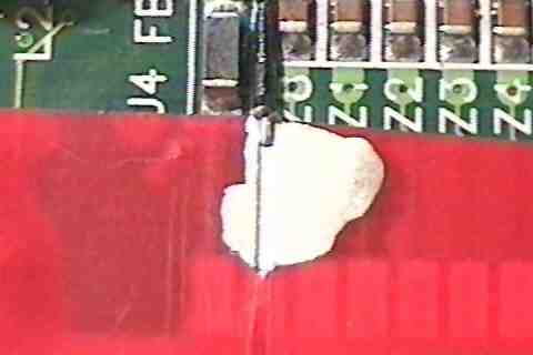
completely after the case is closed. Now to the tricky part. Use some tape
to mask a thin path from the wire straight to pin 9 of the serial port,
it look like picture2 then:
. |
. |
| Make sure the edges are firmly pressed onto the board, so the paint
can't reach under the tape. Then apply the paint *carefully* from the top
of the serial pad to the wire. Take special care not to short the wire
to the ground ferrit (J4). Wait a few minutes (or until the paint is dry)
and remove the tape. You should now have a perfect connection from pad
9 to the resistor. From there, just run another short wire to the positive
batterie terminal. When you did everything right, you should be able to
measure the battery voltage between pin 10 (ground) and pin 9. That's it
for the Palm.
. |
|
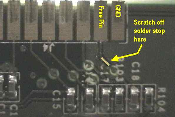
. Modifying the Palm III . The modification of the new Palm III is even easier, since 3Com was kind enough to connect an empty lead to the unused pad. So please read the section of 'How to modify the old Palms' and then forget all about the messy part with the silver paint :). Instead look at the image below and locate lead on your board. Right below the yellow arrow on the image, the lead disappears to the other side of the board and there it ends with a little golden test pad. But unfortunately we can't use that to solder a wire, since it is the area where the key contact rubber is located. And that should lie absolutely flat - so *no solder* on that side! Instead, scratch off the solder stop mask at the marked position. Take care that you don't scratch off the solder stop from the GND-layer left and right of the lead. It helps to prevent shorts, later when you have to solder your wire! . |
. |
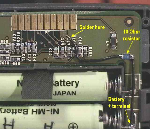
| The rest is easy. Solder a little wire, possibly parallel on the scratched
spot. It's up to you, whether you want to add the 10 Ohm resistor or not.
You could also solder the wire directly to the battery lead, but be aware,
that an accidently short between pin 10 and 9 for example will vaporize
the
little piece of lead between your wire and pin 9, not to talk about other
damages!! A 10 Ohm resistor won't harm and it'll limit the current to a
non-dangerous value. I fixed the SMD resistor (size 1206) with a *tiny*
drop of hot glue - it isolated and is removable. Finally solder the wire
- either from the resistor or directly - to the positive battery terminal.
It's a good idea to run the wire in about a 5mm (1/5 inch) distance along the battery compartment (like on the image). Look where the case back presses on the board when the case is closed, then you know why. . |
. |
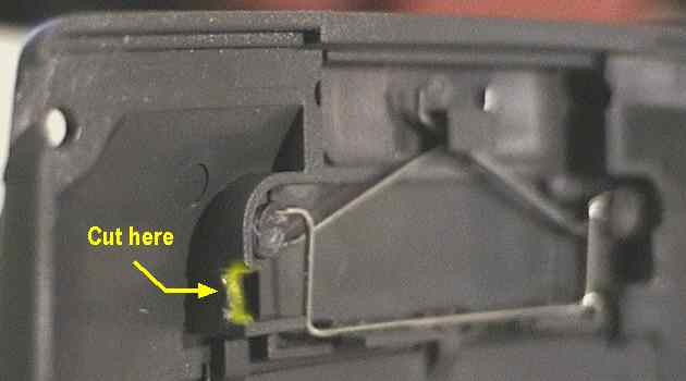
| For this reason, you also have to do an additional, little case modification.
Below you see an image of the case back. The housing of the RS-232 cover
spring presses directly on the board when the case is closed. So the wire
would be squeezed and/or the case wouldn't close properly. Just take a
sharp knife or a cutter and cut a little notch where it's marked on the
image. When closing the case, try to take care that the wire is running
through that notch. Done!
. |
. |
|
. Last updated: March 23rd, 2000 Copyright © 1997-2000 by Peter Strobel, all rights reserved. |